My earlier design which used an ESU LokPilot as the decoder was proving to be erratic as it depended on counting pulses which with a lot of tinkering was still not reliable. I was contacted by a fellow railroader from Canada about using a Lenz System instead of the ESU ECoS and that got me thinking. On vacation from work for a few days, I found a perfect use for the 4 AM slot of my insomniac life. I happened to see a short but fascinating video by Woodsetts Central which reminded me of the Marklin control protocols where unique switch addresses are used to direct the turntable to various tracks. So I rewrote the command interpreter and created a turntable track diagram from ESU graphics. Woodsetts’ video explains many of the steps, but I will enumerate them. End result, reliable DCC control of the turntable which is much better than my earlier iteration. I am providing here the files for the current setup at the bottom of the page. The Eagle board for this setup needs updating and I will post soon. If any reader can improve on this design please message me.
For the design of the controller refer to my original post. Here we will discuss the programming and configuration of the ECoS system.
The Marklin system is best understood by reading the manual of the Littfinski TT-DEC decoder designed and available from Littfinski DatenTechnik (LDT). One table in the manual pretty much sums it all:
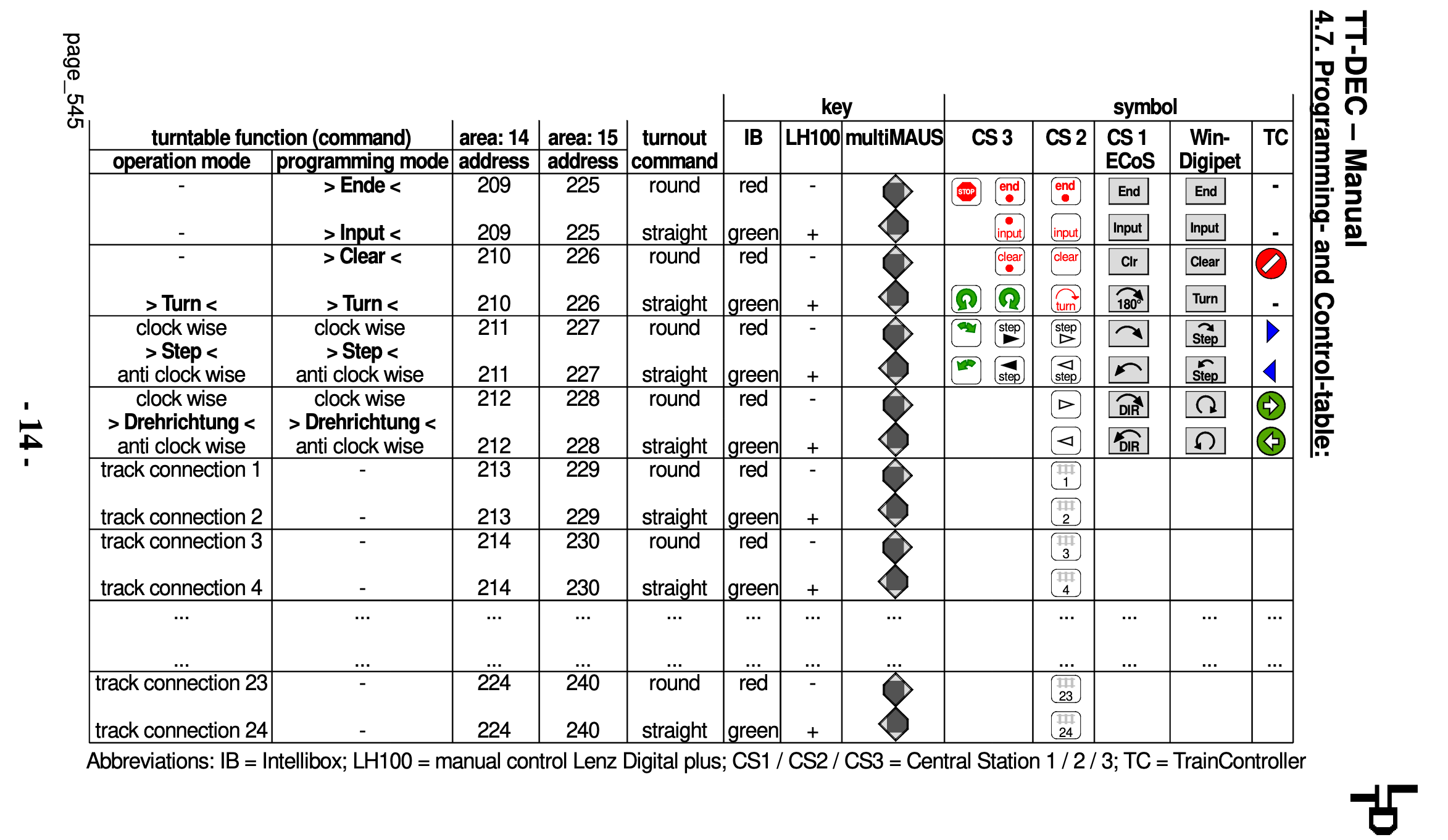
So first I programmed individual accessories, using a two-state dummy button for each of the connected tracks (you can use all 36 if you so desire). Assigning address 225-249 to the tracks I am actually using was all I needed.
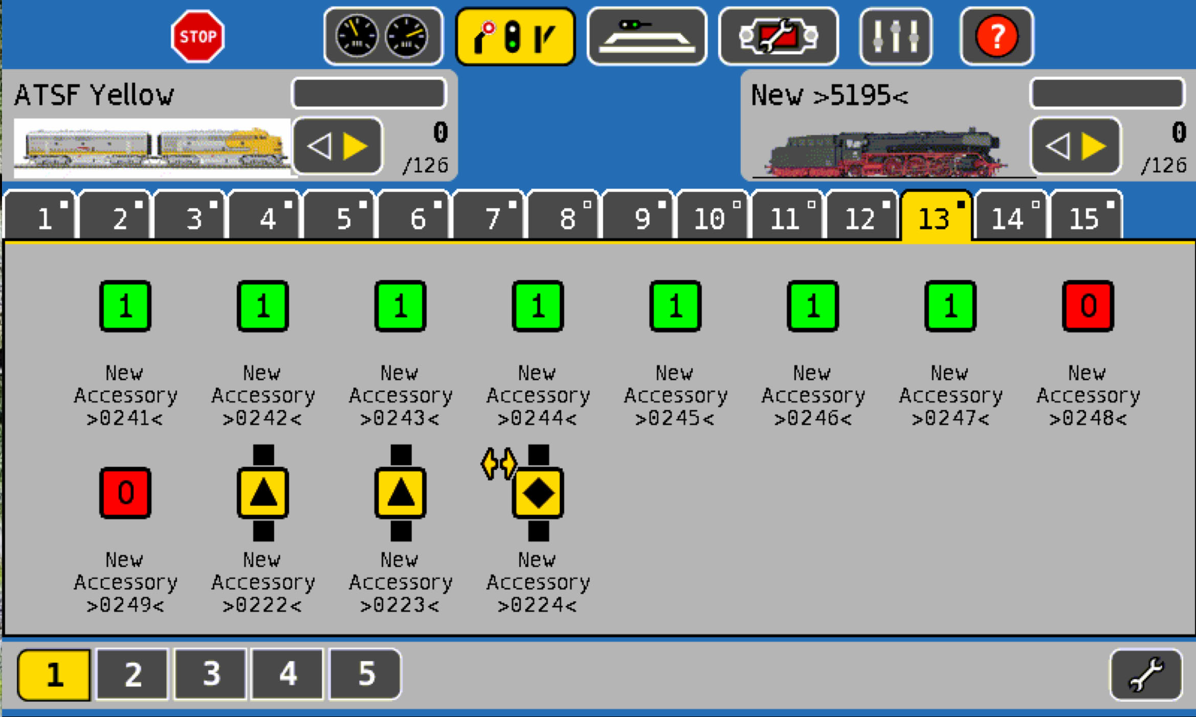
Then I added three additional accessories at address 222 for clockwise single track advance, 223 for counterclockwise single track move, and 224 for a 180-degree bridge turn. As you can see the symbols were used creatively to create the best representation I could. Finally, I created a track diagram for the turntable.

To modify the command interpreter Arduino, two parts are needed, first the DCC signal has to make it to a digital pin on the Arduino, through an Optocoupler otherwise the voltage on the DCC will destroy the Arduino. Rudy’s website is an excellent source of this information.

Once the signal is read by Arduino, I modified Rudy’s DCC sniffer code to listen for Accessory commands specific to the addresses and move the turntable as needed, clockwise, counter-clockwise, 180 degrees, or ‘go-to’ a specified track. In fact, this setup has a unique advantage that it is possible to incorporate turntable movement into routes. I plan to experiment with that idea.
Files for the project can be found in the Github repository linked here.